An electric rotary actuator is an electromechanical device that converts electrical energy into precise angular rotational motion, delivering high torque across specific movement arcs or continuous rotations. By combining an electric motor, a speed-reducing gear train, position feedback sensors, and control electronics, these actuators automate motion in everything from industrial valves and robotic joints to solar tracking systems.
Quick Take
Electric rotary actuators provide high positioning accuracy, clean operation, and programmable velocity control without requiring compressed air infrastructure or hydraulic fluids. While they carry higher initial component costs and lower speed-to-torque ratios than pneumatic cylinders, their energy efficiency and network connectivity make them the preferred choice for modern automated processes. Selecting the right model requires matching peak torque, duty cycle rating, enclosure protection (IP rating), and control interface protocols to the operating environment.
| Actuator Attribute | Key Specification / Capability | Primary Advantage |
|---|---|---|
| Motion Profile | Quarter-turn (90°), multi-turn, or continuous rotation | Flexible angular motion tailored to specific mechanical loads |
| Control Precision | Up to sub-degree angular accuracy via encoders | Eliminates manual alignment and overshooting in closed loops |
| Energy Profile | Power consumption only during active movement | Lower lifetime operating costs compared to pneumatic lines |
| Environmental Protection | IP65 to IP68, NEMA 4/4X, ATEX explosion-proof options | Reliable performance in harsh, outdoor, or hazardous washdown settings |
How Electric Rotary Actuators Work
At its core, an electric rotary actuator operates on electromagnetic conversion principles. When an electrical signal—such as direct current (DC), alternating current (AC), or a pulse-width modulated (PWM) voltage—is applied to the stator windings of an internal motor, it generates a rotating magnetic field. This magnetic field forces the rotor to spin at high speeds with relatively low inherent torque.
Because most industrial and mechanical machinery demands substantial rotational force rather than high motor speeds, the rotational output passes directly into an internal gear reduction system. The gearbox reduces shaft RPM while proportionally multiplying the available torque. This multiplied force is transferred to an external output drive shaft or flange, moving the attached load through a predetermined arc or continuous loop.
To maintain precise positioning, modern units utilize continuous closed-loop feedback. Internal feedback sensors track the shaft’s real-time position and transmit this data back to an onboard microprocessor or central PLC controller. If external resistance or inertia causes the output shaft to drift from its target angle, the control circuit adjusts motor current and direction instantly to correct the error.
Core Components of an Electric Rotary Actuator
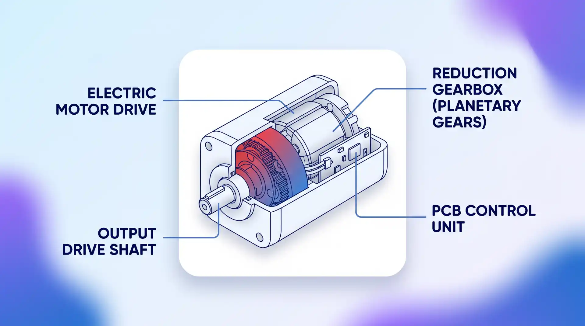
Understanding the internal construction of an electric rotary actuator simplifies troubleshooting, specification, and maintenance planning. The assembly consists of five primary functional subsystems:
1. Electric Motor Drive
The electric motor serves as the primary power unit. Depending on application demands, manufacturers utilize different motor topologies:
- Brushed DC Motors: Cost-effective and simple to control via basic polarity reversals, ideal for light-duty or price-sensitive applications.
- Brushless DC Motors (BLDC): High torque density, higher energy efficiency, and extended service life due to the absence of physical brushes.
- Stepper Motors: High holding torque at low speeds and precise incremental stepping without requiring complex position encoders, making them effective for stepper motor control setups.
- Servo Motors: Delivers exceptional acceleration, high-speed response, and dynamic closed-loop positioning across variable speed profiles.
2. Reduction Gearbox Mechanism
Because high-speed electric motors produce insufficient torque for heavy industrial tasks, reduction gearboxes are integrated into the drive stack. Common mechanical arrangements include planetary gear sets for high power density in compact profiles, spur gear systems for straightforward mechanical transfer, and worm gear drives. Worm gear mechanisms offer the added structural advantage of self-locking capabilities, preventing external loads from back-driving the motor when unpowered.
3. Position and Velocity Feedback Sensors
Precise motion control relies on real-time feedback mechanisms. A simple feedback control system using potentiometers or optical encoders monitors angular velocity and exact position, continuously outputting telemetry to the driver to maintain target positioning under changing mechanical loads.
4. Control Electronics and Communication Interfaces
Modern industrial actuators feature integrated driver electronics capable of processing analog control signals (4–20 mA current loops or 0–10 V DC voltage signals) as well as digital fieldbus protocols such as Modbus RTU, CANopen, or EtherNet/IP. These interfaces allow the actuator to receive position setpoints, broadcast operational status, and log diagnostic alerts to a central Supervisory Control and Data Acquisition (SCADA) system.
5. Housing and Mechanical Mounting Interface
The outer housing protects sensitive electronics and gears from environmental contaminants, moisture ingress, and impact. For process automation and industrial valve control, the drive connection and bolt-hole configuration usually conform to international standardized mounting patterns, such as ISO 5211 flange dimensions, ensuring mechanical interchangeability across component manufacturers.
Types of Electric Rotary Actuators
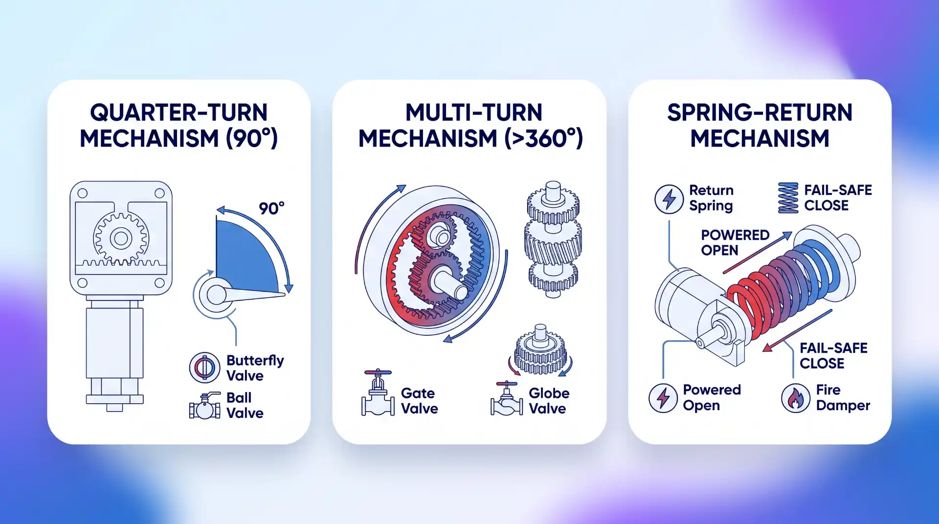
Rotary actuators are categorized based on their rotation range, duty cycle capability, and fail-safe mechanisms:
Quarter-Turn (90-Degree) Actuators
Quarter-turn actuators restrict motion to a 90-degree angle. They are the standard drive mechanism for quarter-turn fluid control elements, such as ball valves, butterfly valves, plug valves, and HVAC air dampers. External mechanical travel stops are often built into the housing to prevent over-rotation and mechanical binding.
Multi-Turn and Continuous Rotation Actuators
Multi-turn actuators can rotate through multiple 360-degree cycles. They are designed for applications requiring long linear travel through rotational leadscrews—such as multi-turn gate valves, globe valves, and adjustable linear slides—or continuous positioning tasks like indexing tables and conveyor alignment diverters.
Fail-Safe and Spring-Return Actuators
In safety-critical industrial processes, a total power outage must not leave valves or control dampers stuck in an unsafe state. A spring-return fail-safe electric actuator utilizes an internal mechanical spring that compresses during normal motorized operation. If line power drops, an internal latching mechanism releases, allowing the stored spring energy to drive the actuator to a pre-defined safe position (fully open or fully closed). Alternatively, battery-backup packs (UPS) are integrated to drive the unit safely to its home state during emergencies.
Key Applications Across Major Industries
Versatile force distribution and smart control interfaces enable electric rotary actuators to perform pivotal tasks across a broad range of sectors:
Automotive Systems
Modern automobiles rely extensively on compact DC rotary actuators for occupant comfort and safety systems:
- Power Windows & Side Mirrors: Compact gearhead motors drive window regulators and adjust side-view mirror angles reliably.
- Ergonomic Seat Positioning: Precision electric motors drive multi-axis seat reclines, lumbar supports, and height adjustments.
- Active Aerodynamics & HVAC: Micro-actuators open and close air duct blend doors and manage active front grille shutters to optimize drag coefficient and engine cooling.
Aerospace and Aviation
Flight control systems require lightweight, vibration-resistant, and high-reliability components. Electric rotary actuators drive trim tabs, primary rudder controls, landing gear latch doors, and UAV payload pan-tilt gimbals where hydraulic piping would add excess weight and maintenance overhead.
Industrial Automation and Manufacturing
In automated production lines and process facilities, rotary units deliver dependable performance for:
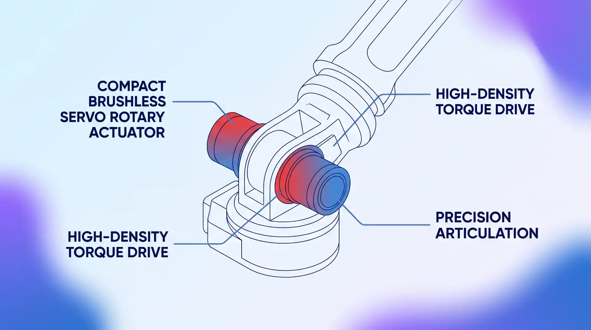
- Robotic Articulation: High-performance brushless servo rotary actuators in robot joints provide smooth, multi-axis arm rotation with sub-millimeter positional repeatability.
- CNC Machining & Tooling: Rotary indexing tables drive precision tool changers and multi-axis workheads during complex metal-milling operations.
- Equipment Maintenance: Integrating electric actuators into heavy machinery reduces overall downtime and supports routine machinery servicing in manufacturing by replacing wear-prone mechanical linkages with self-diagnosing digital units.
Renewable Energy Generation
Renewable power systems depend heavily on precise tracking mechanisms to maximize generation yield:
- Solar Tracking Systems: Commercial solar farms utilize intelligent solar tracking actuators on single-axis or dual-axis arrays to tilt photovoltaic panels toward the sun throughout the day, increasing total energy output by up to 30% over fixed installations.
- Wind Turbines: Rotary actuators control wind turbine blade pitch angles to regulate rotor speed under gusting wind conditions and drive nacelle yaw drives to keep the turbine aligned with wind direction.
Agricultural Machinery
Modern precision agriculture uses ruggedized 12V and 24V electric rotary actuators on combine harvesters, seeders, and chemical sprayers. They dynamically adjust plow height, regulate fertilizer dispersal gate valves, and fold sprayer booms remotely from the cab without manual hydraulic coupling.
Electric vs. Pneumatic vs. Hydraulic Rotary Actuators
Choosing between electric, pneumatic, and hydraulic rotary motion control requires evaluating infrastructure cost, force density, precision, and environmental conditions:
| Factor | Electric Rotary Actuator | Pneumatic Rotary Actuator | Hydraulic Rotary Actuator |
|---|---|---|---|
| Power Source | Electricity (AC/DC) | Compressed air supply | Pressurized hydraulic fluid |
| Positional Accuracy | Very High (Sub-degree closed loop) | Low to Moderate (Hard stops) | Moderate to High |
| Torque Density | Moderate | Low to Moderate | Extremely High |
| Energy Efficiency | High (Consumes power on demand) | Low (Compressor losses) | Moderate (Continuous pump operation) |
| Infrastructure Cost | Low (Standard wiring) | High (Requires air lines/dryers) | High (Requires pumps/reservoirs) |
| Cleanliness / Environment | Clean, quiet, zero fluid leaks | Exhaust air noise, particulate discharge | Risk of fluid leaks and contamination |
Selection & Sizing Criteria for Engineering Applications
To avoid premature component failure or under-powered operation, engineers must calculate several critical operational metrics prior to specifying an electric rotary actuator:
- Required Operating Torque: Calculate both break-away torque (the force needed to unseat a stuck valve or move a static load) and continuous running torque. Apply a minimum safety factor of 1.3x to 1.5x above peak calculated torque to prevent motor stalling.
- Speed and Duty Cycle: Verify the required travel time per 90-degree rotation or full stroke. Ensure the chosen unit’s duty cycle rating (e.g., S2 short-time duty vs. S1 continuous duty) accommodates the operating frequency without exceeding the motor windings’ thermal limits.
- Environmental Rating: Match the housing enclosure to the environment. Select industrial IP-rated enclosures such as IP67 for temporary submersion or explosion-proof housings (ATEX/IECEx) for combustible gas atmospheres.
- Control and Bus Compatibility: Ensure the actuator’s internal controller matches your master controller’s signaling scheme, whether using simple relay contacts, PWM motor modulation, or digital fieldbus communication.
Common Failure Modes and Troubleshooting
Despite their long service lives, electric rotary actuators can encounter operational failures in demanding industrial environments. Understanding these failure modes allows maintenance teams to recover quickly:
- Thermal Overload Tripping: Continuous duty cycles exceeding the rated operating profile lead to excessive heat accumulation, triggering internal thermal switches. Fix: Allow the unit to cool, re-verify load torque, and select a motor rated for continuous duty or equipped with active thermal sinking.
- Gear Backlash and Mechanical Play: Repeated high-cycle shocks or wear on internal spur gears create positional slop at the output shaft. Fix: Inspect gearbox wear, re-calibrate zero-position offsets, or replace worm/planetary drive assemblies.
- Position Signal Drift: Electrical noise on analog 0–10V feedback wiring or dirty optical encoder disks can cause position drift and hunting. Fix: Use shielded twisted-pair wiring for signal lines, check earthing grounds, or re-zero encoder reference points.
- Back-driving Under Static Load: When unpowered, heavy eccentric loads can back-drive non-locking gear trains. Fix: Install an electromagnetic motor brake or retrofit the system with a self-locking worm gearbox.
Key Takeaways
- Electric rotary actuators turn electrical signals into controlled rotational movement by integrating an electric motor, reduction gearing, feedback sensors, and control circuitry into a compact housing.
- They deliver high precision, excellent energy efficiency, clean operation, and seamless integration with industrial PLCs and IoT automation networks.
- Common configurations include quarter-turn (90°), multi-turn, continuous rotation, and spring-return fail-safe designs.
- Key sizing requirements include peak torque with safety factors, duty cycle thermal limits, IP enclosure protection, and interface signal compatibility.
Frequently Asked Questions
What is the main difference between a linear and a rotary electric actuator?
A linear actuator produces force along a straight line (push/pull motion) typically using a rotating leadscrew driving a threaded nut. A rotary actuator produces angular torque directly around a central rotational axis over a set rotational arc or continuous rotation. For a deeper breakdown of mechanism mechanics, review our guide on linear vs. rotary actuators.
How does a fail-safe electric rotary actuator work during a power failure?
Fail-safe electric rotary actuators utilize an internal mechanical spring or an integrated battery backup pack. During normal powered operation, the motor holds the spring under compression (or keeps the battery charged). When incoming electrical power is lost, the spring or battery automatically releases its energy to rotate the output shaft to a safe emergency position.
Can electric rotary actuators be used for continuous 360-degree rotation?
Yes. While many valve actuators are restricted to 90-degree quarter-turn operation, multi-turn and continuous-rotation electric actuators feature specialized motor assemblies and slip rings or absolute multiturn encoders designed for continuous 360-degree rotation.
How do I integrate an electric rotary actuator with a PLC?
Actuators connect to a PLC through analog signals (4–20 mA or 0–10 V) or digital communication protocols such as Modbus RTU, Profibus, or CANopen. The PLC transmits a target position setpoint command to the actuator driver, which executes the rotation and returns a position feedback signal. Learn more in our technical breakdown of PLC fieldbus integration protocols.
