An Autonomous Mobile Robot (AMR) is an industrial material-handling vehicle that uses onboard sensors, laser scanners, and Simultaneous Localization and Mapping (SLAM) algorithms to navigate facilities dynamically without physical guides or external markers. Unlike legacy automated guided vehicles, AMRs perceive environmental changes in real time, calculate alternative routes around unexpected obstacles, and operate safely in shared workspaces alongside human warehouse personnel.
- Infrastructure-Free Navigation: AMRs construct dynamic occupancy grid maps using safety LiDAR, depth cameras, and SLAM algorithms, eliminating the need for floor tape, magnetic tracks, or ceiling reflectors.
- Certified Shared-Space Safety: Dual-zone optical safety fields and safety PLCs comply with ANSI/RIA R15.08 and ISO 3691-4:2023 standards, enabling legal, collision-free collaboration in human-occupied aisles.
- Open Fleet Interoperability: Modern fleets leverage the VDA 5050 open interface over MQTT and JSON to orchestrate multi-vendor robots under a single warehouse management system without vendor lock-in.
- Pragmatic Financial Payback: AMR rollouts deliver capital payback within 12 to 24 months by cutting associate walking transit time by 50% to 70%, with flexible Robotics-as-a-Service models smoothing upfront expenditure.
Core Engineering: How AMRs Perceive, Map, and Navigate Without Physical Guides
Older automated material-handling systems required facilities to install permanent floor magnets, embedded wires, or reflective optical targets along fixed paths. Modern autonomous mobile robots operate without structural modifications by running real-time spatial awareness software directly on embedded industrial vehicle computers.
LiDAR Scanning and Time-of-Flight Optical Depth Perception
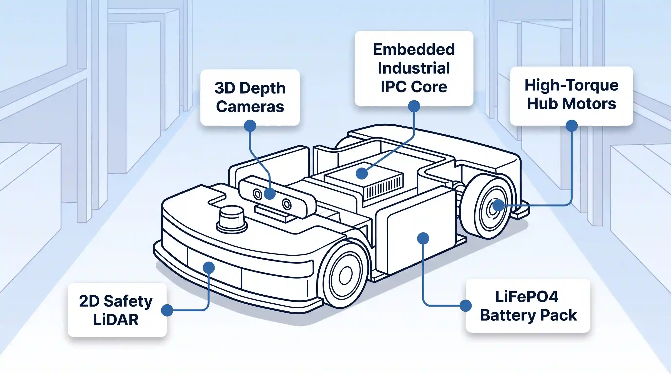
An AMR perceives its physical environment through an integrated array of complementary optical sensors. The primary navigational anchor is a horizontal two-dimensional LiDAR (Light Detection and Ranging) unit mounted near the base of the vehicle, typically 100 to 200 millimeters above the concrete floor. This sensor fires rapid infrared laser pulses across a 270-degree to 360-degree plane, measuring the time of flight for each pulse to bounce off pallets, walls, and structural columns. The resulting point cloud provides precise millimetric distance measurements up to 30 meters away.
Because planar LiDAR scans only a single horizontal cross-section, it cannot detect hazards outside its beam height. To prevent collisions with raised forklift tines, cantilevered pallet loads, or debris lying flat on the floor, AMRs incorporate forward-facing 3D Time-of-Flight (ToF) cameras and structured-light stereo vision sensors. These cameras project an infrared grid into the robot’s immediate forward path, generating a volumetric 3D depth map that captures obstacles from floor level up to two meters in height.
Simultaneous Localization and Mapping (SLAM) and Kinematic Filtering
Raw sensor data is meaningless without an algorithmic framework to determine vehicle coordinates. AMRs solve this through Simultaneous Localization and Mapping (SLAM). When a robot is first introduced to a facility, an operator drives the unit through the aisles via manual joystick control. As the vehicle travels, onboard SLAM software correlates laser range returns with wheel rotation metrics to construct a master two-dimensional occupancy grid map.
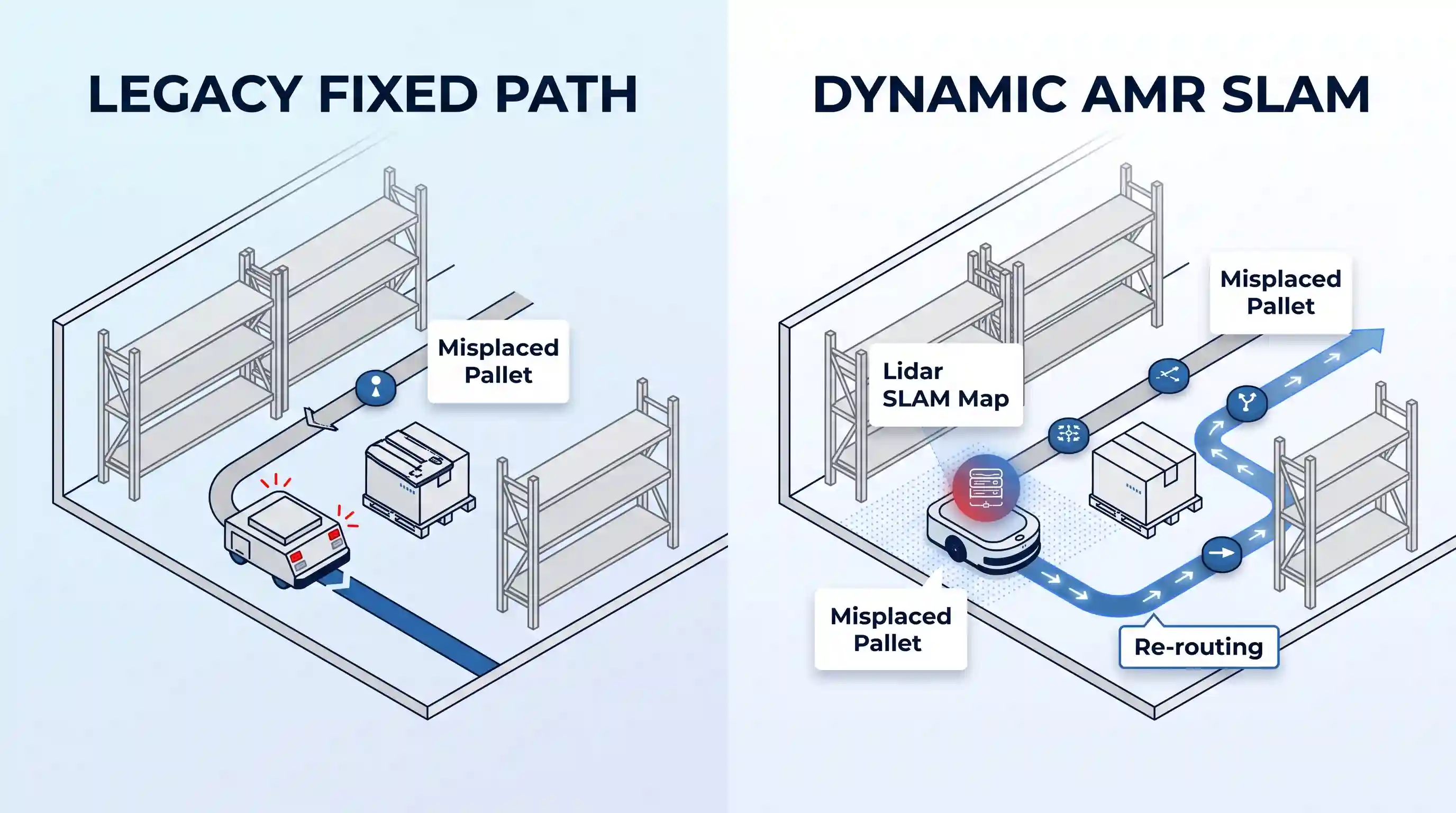
During active production shifts, the AMR matches its live LiDAR returns against this stored reference map. However, industrial warehouse environments change continuously; staging lanes fill with pallets, loading dock doors open and close, and forklifts cross active travel aisles. In robotic kinematics research published by the IEEE Robotics and Automation Society, multi-sensor fusion combining wheel encoders, inertial measurement units (IMUs), and planar laser scanning resolves dead-reckoning drift and prevents localization slippage across slick concrete surfaces.
An Extended Kalman Filter (EKF) processes high-frequency wheel odometry and IMU angular velocity data alongside lower-frequency LiDAR scan-matching updates. If an AMR encounters a newly staged pallet stack that does not exist on its reference map, the algorithmic filter classifies the return as a transient obstacle rather than a permanent architectural wall. The local path planner dynamically plots an alternate spline around the obstruction while remaining aligned with global destination waypoints.
Drive Kinematics, Wheel Odometry, and Floor Traction
Facility layout and payload mass dictate AMR chassis kinematics. Most light-to-medium transport robots (payloads up to 1,500 kilograms) use a differential drive arrangement. This configuration features two high-torque brushless DC hub motors mounted on a central transverse axis, supported by four passive spring-loaded corner casters. By running the drive wheels at identical velocities, the robot moves in a straight line; by rotating them in opposite directions at equal speeds, the robot executes a zero-radius turn within its own footprint, making it well-suited for narrow warehouse rack aisles.
For heavy pallet transport exceeding 1,500 kilograms or applications requiring lateral docking maneuvers, industrial platforms employ steerable traction drives or omnidirectional mecanum wheels. Mecanum wheels feature angled passive rollers around their circumference, allowing vectors of force to propel the vehicle sideways without changing chassis heading. However, mecanum drivetrains require strict floor flatness and exhibit lower energy efficiency than polyurethane solid wheels on differential drives.
Safety Standards and Shared-Space Human Collaboration
Traditional industrial robotic arms operate inside interlocked steel cages that immediately shut down power if a human operator opens an access gate. Autonomous mobile robots cannot rely on physical barriers because their primary operational value stems from traveling through the same physical corridors, loading docks, and picking zones occupied by human warehouse associates.
ANSI/RIA R15.08 Classification of Industrial Mobile Robots
To establish rigorous design and deployment baselines for collaborative mobile platforms, the Association for Advanced Automation (A3) and the American National Standards Institute published the ANSI/RIA R15.08 standard series. The ANSI/RIA R15.08 safety standard establishes legal requirements for risk assessments, hazard zones, and mechanical load stability, organizing vehicles into three distinct technical classes:
-
- Type A (Autonomous Mobile Robot): The standalone mobile drive platform with no application-specific tooling. It is certified for autonomous point-to-point transit while carrying static payloads on its top mounting deck.
- Type B (AMR with Passive or Active Attachments): An AMR platform integrated with passive mechanical hardware (such as towing hitches or static shelving) or active powered tooling (such as motorized roller conveyors or hydraulic pallet lifting tables). The addition of active attachments alters the center of gravity and braking distance, requiring secondary validation.
-
- Type C (Mobile Manipulator): A multi-axis articulated robotic arm mounted on an autonomous mobile platform. Type C systems introduce complex dynamic tipping moments and require synchronized safety interlocking between arm trajectory and platform motion. Facilities requiring high-precision carton manipulation should review our dedicated analysis of robotic each-picking end-effectors.
ISO 3691-4:2023 Dynamic Safety Field Switching
International safety standards for driverless industrial trucks published under the ISO 3691-4:2023 standard define the functional architecture required to protect personnel in shared workspaces. Vehicles must establish two continuous safety zones projected by safety-rated LiDAR sensors:
- Warning Field (Outer Zone): A wide optical detection perimeter that detects approaching personnel or vehicles. When a human walks into the warning field, the robot sounds an audible chime, activates pulsing LED indicators, and decelerates from full transport velocity (typically 1.5 to 2.0 meters per second) down to a cautious creep speed (0.3 meters per second).
- Protective Field (Inner Stop Zone): A fail-safe boundary calculated around the physical perimeter of the chassis. If an associate steps directly into the protective field, the system bypasses software logic entirely. Safety-rated relays de-energize the drive motors and engage mechanical friction brakes to bring the platform to a controlled stop before physical contact occurs.
Under ISO 3691-4:2023, safety field dimensions cannot remain static. As an AMR accelerates, carries heavier payloads, or initiates a turning radius, the onboard safety PLC dynamically switches field profiles. When traveling at top speed in a straight corridor, the forward protective stop field expands outward to account for mechanical braking distances under wet or dusty concrete conditions. When maneuvering into an aisle shelf to drop a bin, the protective field contracts to allow tight clearances without triggering nuisance stops.
Fail-Safe Electrical and Mechanical Architectures
Software operating systems like Linux and ROS (Robot Operating System) are prone to occasional software hangs, latency spikes, or computational crashes. Because uncertified operating systems cannot be trusted with human life safety, industrial AMRs separate high-level navigation software from low-level safety execution.
All safety-critical inputs (including safety laser scanners, bumper touch sensors, and dual-channel red mushroom emergency stop buttons) wire directly into an onboard Safety PLC certified to ISO 13849-1 Performance Level d/e (PLd/PLe) and IEC 62061 SIL 2/SIL 3. If the master industrial PC running the SLAM navigation stack freezes, the isolated Safety PLC independently maintains vehicle safety limits, cutting motor current and engaging electromechanical holding brakes the instant a safety breach occurs.
Fleet Management Systems: Orchestrating Multi-Robot Warehouse Traffic
Deploying a single AMR is a straightforward robotics exercise; orchestrating a coordinated fleet of 50 to 200 autonomous vehicles across a 500,000-square-foot fulfillment center requires a centralized software control layer. Modern mobile robotics function as edge endpoints within broader logistics architectures, as detailed in our comprehensive supply chain technology guide.
Master Fleet Controllers vs. Onboard Intelligence
Warehouse automation relies on a distributed computing model that balances edge independence with centralized traffic optimization:
- The Onboard Edge Controller: Each robot handles its own millisecond-level trajectory calculation, immediate obstacle circumvention, safety field monitoring, and motor torque regulation. If wireless connectivity drops, the robot safely completes its active movement block or decelerates to a stop.
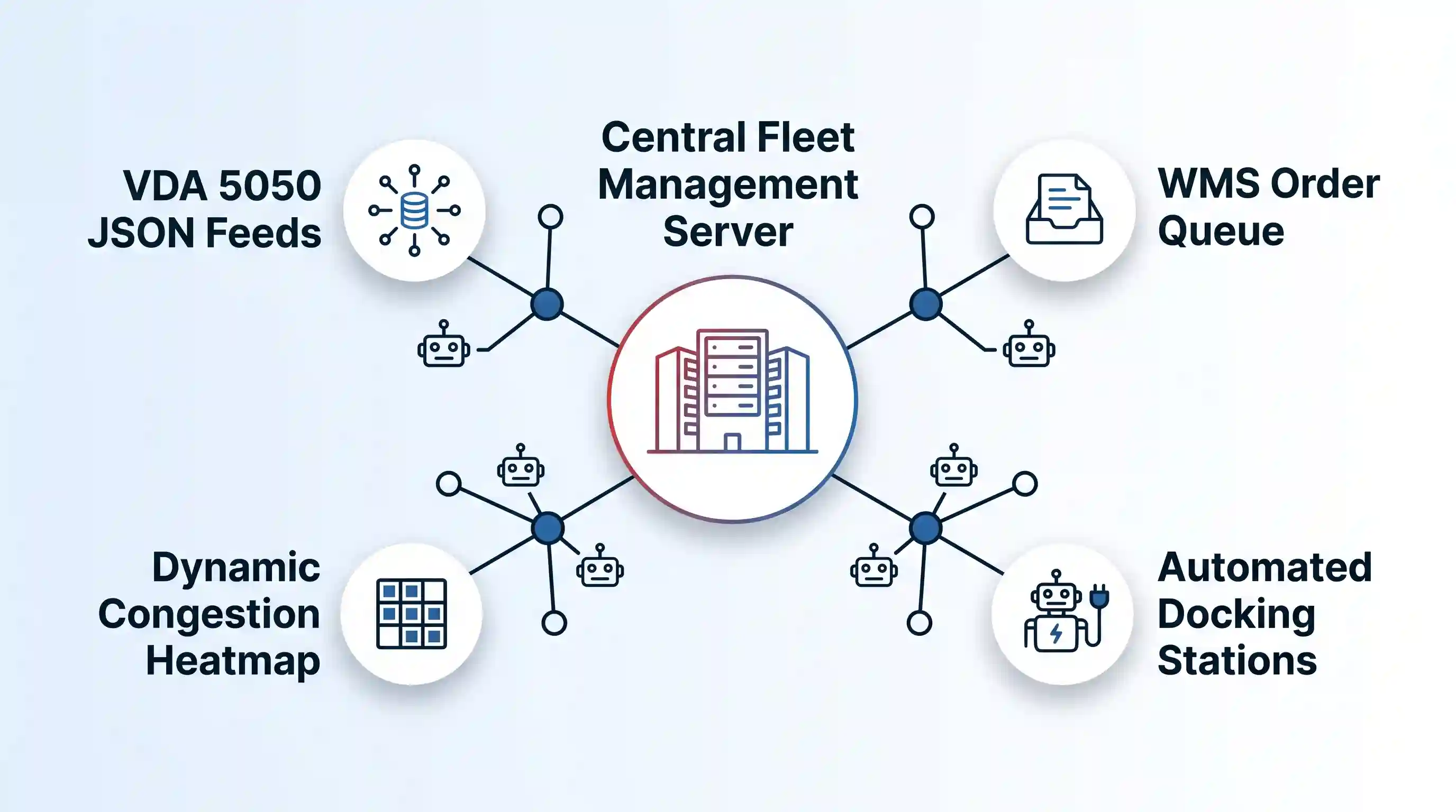
- The Master Fleet Controller (MFC): A centralized server (hosted on-premises or in the cloud) acts as the global air traffic controller. The MFC tracks real-time spatial coordinates for all units, dynamically reserves intersections to prevent gridlock, manages battery charging rotations, calls freight elevators, and assigns transport missions based on geographic proximity.
The VDA 5050 Standard and Multi-Vendor Interoperability
Historically, commercial warehouse robotics suffered from vendor lock-in. If a logistics facility purchased twenty small sorting AMRs from one robotics manufacturer, they could not easily integrate heavy pallet-moving AMRs from a different manufacturer without running two completely separate, conflicting fleet management applications that competed for aisle access.
To break this proprietary barrier, the German Association of the Automotive Industry (VDA) and the VDMA Materials Handling Association created the VDA 5050 standard. As documented by the VDA 5050 interface specification, an open MQTT message broker and JSON payload structure allows a unified third-party master fleet controller to communicate with heterogeneous mobile robots from different manufacturers.
Under VDA 5050, the master controller dispatches standardized order messages consisting of graph nodes (target waypoints) and edges (connecting paths) with explicit velocity limits and orientation rules. The individual robots translate these abstract topological paths into their own unique drive kinematics, reporting back uniform state messages covering position coordinates, battery health, load presence, and active diagnostic trouble codes.
Enterprise WMS and MES System Integration
Fleet management software does not operate in isolation. It sits between physical ground hardware and upstream enterprise planning platforms, specifically Warehouse Management Systems (WMS), Warehouse Execution Systems (WES), and Manufacturing Execution Systems (MES). Communication flows over secure RESTful APIs and bidirectional WebSocket connections.
When an online customer order drops into the WMS, the system generates pick orders and transmits transport requests to the fleet manager. The fleet manager calculates which idle AMR has sufficient battery state of charge, dispatches the robot to the appropriate pick aisle, and notifies the associate’s wearable terminal that a transport pod is positioned for loading. While AMRs handle flexible horizontal floor transit, vertical high-density pallet storage is governed by dedicated AS/RS high-bay warehouse engineering systems.
Financial Engineering: Calculating True ROI, CapEx vs. RaaS, and Payback Timelines
Investing in warehouse mobile robotics requires balancing mechanical capabilities against balance-sheet practicalities. Operations executives must weigh significant initial capital deployment against predictable operational labor savings and throughput improvements.
Capital Expenditure (CapEx) vs. Robotics-as-a-Service (RaaS)
Organizations deploy warehouse robotics through two standard financial models:
- Traditional CapEx Procurement: The facility purchases robotic hardware, software licenses, and charging docks outright. Industrial deck-load AMRs typically cost between $30,000 and $55,000 per base chassis, while heavy pallet lifters range from $70,000 to $110,000 per unit. Facilities must also account for upfront site mapping, system integration fees ($40,000 to $150,000), and annual software maintenance contracts (typically 12% to 18% of original software license value). CapEx delivers the lowest total cost of ownership over a five-to-seven-year operational horizon.
- Robotics-as-a-Service (RaaS) OpEx: Under the RaaS framework, the automation vendor retains hardware ownership and leases the fleet for a predictable monthly operational fee, usually $1,500 to $3,500 per robot per month. Subscriptions bundle hardware, software licenses, remote fleet health monitoring, and complete parts replacement. RaaS allows third-party logistics (3PL) providers to match automation costs directly to customer contract terms while scaling fleets up or down to absorb seasonal holiday fulfillment surges.
Quantifiable Labor Payback and Throughput Gains
The primary economic driver for mobile warehouse robotics is the reduction of non-value-added travel time. In conventional manual order picking operations, warehouse associates spend between 50% and 70% of their active shifts walking empty carts across long concrete aisles. By assigning horizontal transit tasks to AMRs, human workers remain stationed within localized picking zones, performing value-added order consolidation and carton induction.
Industry benchmarks compiled by material handling research at KNAPP supply chain insights indicate that eliminating transit walking doubles or triples picking productivity per associate, yielding capital payback between 12 and 24 months. In operations running two or three consecutive shifts daily, compressed amortization schedules routinely deliver verified payback in under 14 months.
Hidden Operational Costs and Facility Dependencies
Financial models must account for several facility preparation and maintenance variables that are frequently omitted from vendor sales proposals:
- Concrete Floor Quality and Expansion Joints: While AMRs do not require embedded magnetic tracks, they do require structural floor integrity. Concrete spalling, unsealed expansion joints, and excessive slope variations accelerate polyurethane tire wear and trigger false-positive obstacle detections from low-mounted LiDAR sensors. Facilities often spend $10,000 to $35,000 repairing floor joints before fleet commissioning.
- Industrial Wi-Fi Roaming and AP Density: Fleet controllers require unbroken connectivity for mission dispatch. When a robot transitions between wireless access points across metal warehouse racking, roaming packet drops exceeding 150 milliseconds can force the vehicle into an autonomous safety pause. Upgrading warehouse wireless networks to industrial Wi-Fi 6 standards with optimized 5 GHz cell overlap is a common prerequisite.
- Fast-Charging Electrical Infrastructure: High-amperage direct-current copper pad contact docks demand dedicated 480V three-phase electrical drops, requiring distribution panel upgrades near high-traffic intersections. Operations managers track live vehicle uptime, transit times, and maintenance intervals by piping fleet telemetry into business intelligence software, as outlined in our guide on how to use Tableau.
Comparison Matrix: AGVs vs. AMRs vs. Fixed AS/RS
Selecting the optimal warehouse automation technology requires matching facility throughput requirements and operational flexibility against structural capital constraints.
| Technical Characteristic | Automated Guided Vehicles (AGVs) | Autonomous Mobile Robots (AMRs) | Fixed Rail AS/RS Cranes |
|---|---|---|---|
| Navigation Mechanism | Physical magnetic tape, optical floor tape, or reflective laser targets. | Infrastructure-free SLAM using 2D LiDAR, 3D ToF cameras, and wheel odometry. | Rigid structural steel guide rails and fixed rack-mounted mast tracks. |
| Obstacle Avoidance | Stops and waits indefinitely until human operator clears the path. | Detects obstacle dynamically and recalculates an alternate route around it. | No obstacle avoidance; locked to closed, fenced-off structural crane aisles. |
| Facility Modifications | Moderate; requires floor cutting, tape installation, or laser target surveys. | Minimal; zero physical guide markers required; software-only map tagging. | Extensive; requires specialized high-tolerance concrete slabs and structural steel buildouts. |
| Deployment Lead Time | 3 to 6 months. | 4 to 8 weeks. | 12 to 24 months. |
| Operational Scalability | Difficult; adding new pickup stations requires physical tape and marker re-laying. | Highly flexible; new drop zones and robots can be added via software updates. | Inflexible; vertical crane capacity cannot be expanded without new structural aisles. |
| Initial Capital Intensity | Moderate CapEx commitment. | Moderate CapEx with flexible OpEx through RaaS models. | High; multi-million dollar initial capital commitment. |
For aerial inventory audits rather than floor material transport, facilities deploy automated UAV platforms, explored in our analysis of warehouse drone inventory scanning.
Step-by-Step Implementation Blueprint: From Facility Mapping to Full Deployment
Transitioning from manual cart pushing to an automated mobile robot fleet requires a disciplined, phase-gate implementation strategy to prevent production downtime.
- Conduct Environmental and Facility Audits: Survey concrete floor flatness (verifying compliance with ASTM E1155 or DIN 18202 standards), inspect floor expansion joints, measure ambient lighting conditions near loading dock doors to avoid optical sensor blinding, and conduct a detailed RF signal survey to eliminate Wi-Fi dead zones.
- Build the High-Precision Reference Map: Manually navigate a mapping robot across all facility aisles using a wireless handheld controller. Ingest the generated point clouds into fleet software to produce a master 2D occupancy grid. Annotate virtual rules directly onto the map, including one-way traffic lanes, maximum speed zones around pedestrian crosswalks, keep-out zones around chemical storage, and automated charging locations.
- Integrate Enterprise Software Interfaces: Connect the Master Fleet Controller to the host WMS or ERP via RESTful APIs and MQTT message brokers. Test bidirectional handshakes to ensure order generation, inventory pick allocations, bin status verification, and vehicle mission cancellations execute with sub-second latency.
- Execute Isolated Pilot Line Testing: Deploy two to four AMRs within an isolated, single-department pick line. Validate that picking staff interact correctly with onboard tablet user interfaces, verify that safety LiDAR zones switch accurately under full payload acceleration, and audit actual mechanical cycle times against theoretical simulation models.
- Configure Automated Opportunity Charging and Cutover: Position fast-charging copper pad stations at natural dwell points (such as pallet staging queues and pack station return lines). Program automated charging rules so robots dock autonomously whenever their lithium-iron-phosphate battery reserves dip below 30% during shift changes, then scale the full production fleet across all operational zones.
Frequently Asked Questions
What happens when an AMR loses its Wi-Fi network connection?
When an autonomous mobile robot encounters a wireless dead zone, it does not immediately freeze or lose its location. Because SLAM localization and safety laser monitoring run locally on embedded industrial computers, the AMR continues executing its current movement block along its mapped path. If the communication timeout exceeds a pre-configured buffer (typically 5 to 15 seconds) without receiving updated trajectory clearance from the master fleet server, the robot safely decelerates to a controlled stop, illuminates warning beacons, and waits for connection recovery.
How do autonomous mobile robots charge their batteries during production shifts?
Modern AMRs use opportunistic charging rather than manual battery swapping. Vehicles utilize Lithium Iron Phosphate (LiFePO4) or Nickel Manganese Cobalt (NMC) battery chemistries capable of accepting high-current fast charging without thermal degradation. Whenever a robot is idle between mission dispatches or staged at a picking station, it navigates over an automated floor-mounted copper charging pad. High-amperage contacts deliver rapid top-ups, allowing fleets to maintain continuous round-the-clock operations without human intervention.
Can AMRs operate on uneven concrete floors or across floor expansion joints?
AMRs can negotiate minor floor imperfections, but they require higher floor quality than traditional manned forklifts. Most standard industrial AMRs have a maximum ground clearance of 20 to 35 millimeters and can traverse floor seams up to 10 millimeters wide and 5 millimeters deep. Severe expansion joint spalling, cracked slabs, or steep access ramps exceed the suspension travel of rigid drive wheels, which can cause drive slippage, localized odometry errors, or low-clearance LiDAR ground collisions.
How does the VDA 5050 standard resolve traffic conflicts in multi-vendor fleets?
The VDA 5050 standard resolves multi-vendor conflicts by separating global traffic management from individual vehicle kinematics. Instead of allowing proprietary software to control vehicle movements independently, all robots communicate with an agnostic master fleet controller via standardized JSON messages over MQTT. The master controller tracks global coordinate reservations, granting permission for specific robots to traverse shared aisle segments and intersections while ordering lower-priority units to hold position at buffer nodes.
What is the typical operational lifespan of an industrial AMR chassis?
Industrial autonomous mobile robots are engineered for continuous commercial duty cycles, with an expected chassis and drivetrain operational lifespan of 5 to 7 years (equivalent to 20,000 to 35,000 run hours) under structured preventive maintenance schedules. Routine maintenance items include drive wheel tread replacement (every 12 to 18 months), optical sensor lens cleaning and calibration, and suspension pivot inspections. Industrial lithium battery packs typically retain over 80% capacity after 3,000 to 4,000 full charge cycles.

💬 Comments