Effective data center environmental monitoring measures conditions where equipment and infrastructure experience risk, applies equipment-specific thresholds, and sends actionable alarms through a response path that is tested regularly. The objective is not simply to collect readings, but to detect thermal, moisture, airflow, leak, power, and contamination problems early enough to support a timely response.
What an Environmental Monitoring System Must Accomplish
A data center environmental monitoring system combines sensors, communications, data storage, alerting, and operating procedures. It observes physical conditions around information technology equipment and supporting infrastructure, records how those conditions change, and notifies the responsible people when intervention may be required.
Monitoring is distinct from control. A monitoring platform can report that rack-inlet temperature is rising, while a building management system may adjust cooling in response. Neither system replaces properly designed cooling, electrical protection, leak containment, fire detection, or fire suppression.
The most important thermal measurement is usually the condition of the air entering air-cooled equipment. Lawrence Berkeley National Laboratory explains that equipment-intake temperature represents the air on which the electronics depend for cooling. A wall sensor or return-air reading can remain normal while recirculated exhaust creates a hot area at one rack.
This distinction changes the design goal. The system must show what critical equipment is experiencing, not merely whether the room feels comfortable or whether one centrally located thermostat is within range.
1. Define Assets, Failure Modes, and Responsibilities
Begin with the equipment and services that need protection. List the racks, network cabinets, storage systems, power equipment, cooling units, and other infrastructure whose loss could interrupt operations. Then identify how environmental conditions could affect each asset.
A small network closet below a water pipe has a different risk profile from a contained data hall with high-density graphics processing unit racks. The closet may need a rack-inlet temperature probe, a water sensor, power-loss detection, and dependable after-hours notification. The larger facility may also require vertical temperature profiles, airflow measurements, corrosion monitoring, cooling-system integration, and separate thermal zones.
Record who owns each response. Facilities personnel may handle cooling or water isolation, while information technology staff may reduce workloads or shut down equipment. In a colocation facility, the tenant and site operator may control different parts of the response. Those boundaries should be documented before an alarm occurs.
Keep adjacent monitoring functions distinct. Workplace-safety analytics, including platforms such as Protex AI, address a different control problem and should not be treated as substitutes for temperature, moisture, airflow, leak, or power monitoring.
Prerequisites
- An inventory of critical equipment, its location, and its environmental specifications.
- A map of racks, cooling paths, plumbing, drains, power equipment, doors, and other likely failure points.
- Named owners for facilities, information technology, security, and after-hours escalation.
- The manufacturers’ current operating limits for the installed equipment.
2. Choose the Conditions That Reveal Each Risk
Every measurement should correspond to a failure mode and a possible response. Installing every available sensor creates cost and maintenance work without necessarily improving protection.
The following table connects common measurements to their operational purpose. Exact coverage still depends on the room, equipment, cooling design, and consequences of a missed event.
| Measurement | What it can reveal | Useful measurement location | Important limitation |
|---|---|---|---|
| Temperature | Insufficient cooling, recirculated exhaust, obstructed airflow, or a rising equipment load | At representative equipment intakes, with room-level points for context | A room average can hide a local hot area |
| Dew point and relative humidity | Changes in atmospheric moisture and possible condensation or electrostatic concerns | Representative room or zone locations, interpreted with local temperature | Relative humidity changes with temperature and should not be interpreted alone |
| Airflow or pressure | Loss of cooling delivery, bypass air, recirculation, or containment problems | Across relevant aisles, containment boundaries, vents, or cooling paths | A reading at one vent may not represent airflow through a rack |
| Water or other liquid | Condensate, plumbing, roof, drain, or liquid-cooling leaks | Along likely flow paths and below vulnerable equipment or connections | A point sensor detects liquid only when it reaches that spot |
| Power state and load | Loss of utility power, overloaded distribution, or failure of supporting equipment | At relevant circuits, power distribution units, cooling equipment, and monitoring gateways | Power telemetry does not show whether cooling reaches the equipment |
| Particulate or gaseous contamination | Conditions that may foul equipment or contribute to corrosion | At outdoor-air paths or affected equipment zones when the site assessment justifies it | Not every facility needs continuous contaminant instrumentation |
Temperature and moisture
Dry-bulb temperature is the ordinary air-temperature reading produced by most temperature probes. Relative humidity expresses the amount of water vapor in the air relative to the maximum possible at that temperature. Dew point is the temperature at which the air would become saturated and condensation could begin.
Relative humidity can vary across a room as temperature changes even when its moisture content is similar. For that reason, ASHRAE identifies dew point as a more consistent basis for monitoring moisture in data rooms. Relative humidity remains useful, but it should be interpreted alongside dry-bulb temperature and dew point.
Airflow, leaks, power, and contamination
Temperature shows the outcome of many cooling problems, while airflow or pressure measurements can help identify the mechanism. A rising top-of-rack inlet temperature combined with weak cold-air delivery, for example, points toward an airflow problem rather than a room-wide temperature increase.
Leak coverage should follow the paths liquid is likely to take. Point sensors suit a specific collection area, while sensing cable can cover a longer route. Neither design is universally better. Selection depends on the number of possible sources, floor construction, drainage, equipment layout, and the amount of liquid required to trigger detection.
Power monitoring adds useful context. If rack temperatures increase at the same time a cooling unit loses power, the combined event is easier to interpret than either alarm alone. The environmental monitor and its communication gateway also need a power-failure strategy; otherwise, the monitoring system may disappear when it is needed most.
Particulate and gaseous contamination monitoring is risk-dependent. ASHRAE notes that facilities exposed to gaseous contaminants may use periodic copper and silver coupon testing to assess corrosive conditions. A sealed, clean office server room may not need that program, while a site near industrial emissions or one using substantial outdoor air may justify further assessment.
When reviewing commercial catalogs, Sensors should be evaluated by measured quantity, operating range, accuracy, calibration support, output protocol, and failure indication rather than by the number of readings shown on a dashboard.
Fire-system status may also be integrated into a facility monitoring console, but fire detection and suppression are separate life-safety disciplines. Their selection, installation, testing, and maintenance must follow the requirements applicable to the facility and should be handled by qualified specialists.
3. Place Sensors Where Conditions Develop
A sensor should be positioned where it can observe the condition relevant to the equipment or hazard. Convenient wall space is not a sufficient placement criterion.
For air-cooled equipment, start at the rack inlet. A practical survey normally includes readings near the bottom, middle, and top of representative rack faces. This vertical profile can reveal inadequate delivery near the bottom or recirculated hot air near the top.
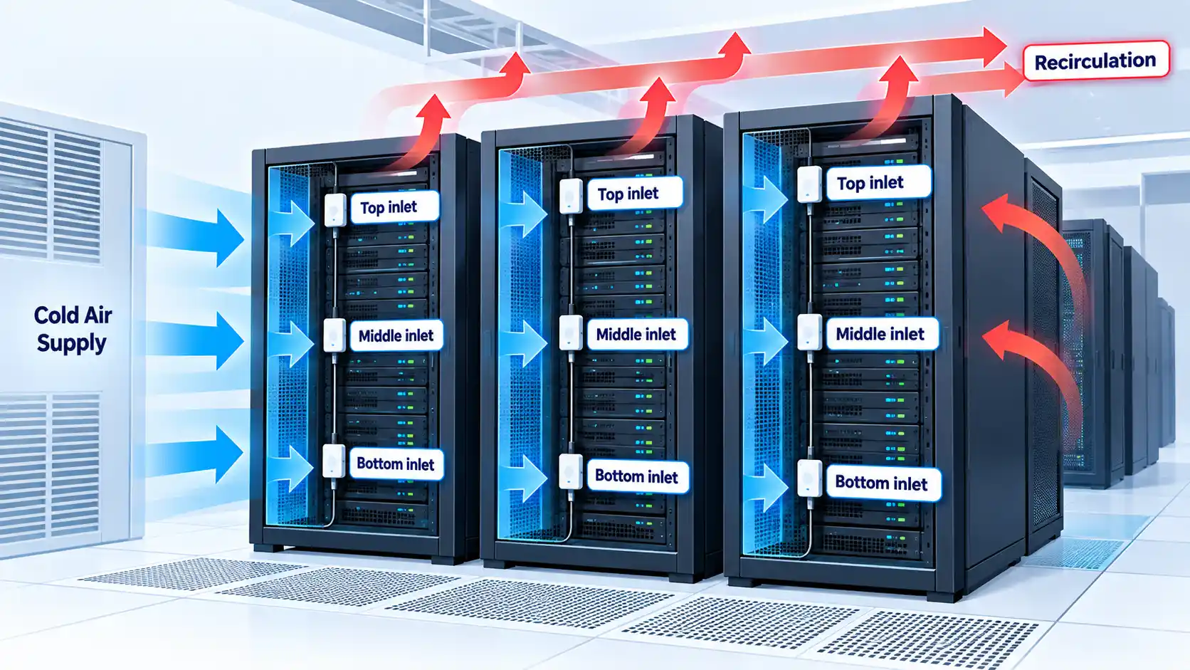
Lawrence Berkeley National Laboratory recommends placing probes close to the perforated rack door and describes reduced-count arrangements using representative racks and top, middle, and bottom positions. Its study demonstrates that thoughtful sampling can reduce sensor count without abandoning useful thermal visibility.
The result should not be interpreted as a universal rule to instrument every second or third rack. The study concentrates substantially on raised-floor environments, and the necessary density changes with rack load, containment, cooling delivery, and acceptable risk. A temporary thermal survey can identify variation before permanent locations are chosen.
Include end-of-row racks, unusually dense racks, known warm areas, and zones near doors or cooling boundaries when they may behave differently. Reassess the layout whenever racks, blanking panels, containment, cabling, supply vents, or major workloads change.
Place leak sensors near cooling units, condensate systems, plumbing entries, drains, roof-risk areas, and liquid-cooling connections. Follow the likely path of the liquid, including slopes and openings in raised floors. Do not install a sensor where normal maintenance repeatedly wets or disturbs it unless the alarm process can distinguish planned work from a genuine incident.
Equipment with narrower environmental requirements may need a separately controlled zone. Both ASHRAE and the European Commission’s data-centre guidance support separating equipment with materially different environmental needs rather than forcing the whole facility to meet the tightest range.
4. Set Targets, Warning Thresholds, and Escalation Rules
Setpoints should begin with the installed equipment’s current documentation and applicable equipment class. Do not copy one temperature or relative-humidity range from a generic checklist and apply it to every site.
The recommended and allowable ranges serve different purposes. The U.S. Department of Energy explains that the recommended range is the normal reliability target, while the allowable envelope describes tested functionality boundaries. Operating continuously near an allowable limit is not equivalent to remaining in the preferred range.
Use separate operational alarm levels when the equipment and monitoring platform support them. A warning identifies drift that should be investigated. A critical alarm indicates that prompt intervention is needed. Emergency shutdown or equipment-protection limits belong to a separate, carefully engineered control process.
Thresholds also need time behavior. A persistence delay requires a condition to remain present before an alarm is sent. Hysteresis requires the measurement to move sufficiently back toward normal before an alarm clears. These controls can reduce repeated notifications when a reading fluctuates around a boundary, but excessive delays can hide a fast-developing event.
Rate-of-change alarms can reveal a rapid cooling failure before an absolute temperature limit is crossed. Missing-data alarms are equally important. A silent or frozen probe should not look like a stable environment.
Do not widen temperature or moisture limits solely to reduce alarm volume. First confirm the equipment class, manufacturer limits, measurement accuracy, sensor position, and time spent outside the preferred range.
The European Commission advises operators to review temperature and humidity settings to reduce unnecessary cooling or moisture control, but it also identifies important limitations. Legacy equipment can restrict the usable range, and higher intake temperatures can increase equipment fan energy. Any setpoint change should therefore be evaluated as a whole-system decision.
5. Build a Reliable Data and Alert Path
A valid reading provides little protection if it cannot reach someone able to respond. Document the complete path from the sensing element to the responder.
Environmental readings may feed a building management system (BMS), data center infrastructure management (DCIM) platform, or network management system (NMS). The platform should preserve the sensor identity, location, timestamp, measurement unit, current value, and alarm state. Historical sensor data becomes more useful when it can be correlated with workload, cooling, maintenance, and power events.
Choose sampling and storage intervals that match the rate at which a harmful condition can develop and the records the organization needs. The system should make a stale reading visibly different from a current reading. Clocks should also be synchronized well enough to reconstruct the sequence of an incident across environmental, cooling, power, and information technology systems.
Consider each dependency:
- What powers the sensor, gateway, network switch, monitoring platform, and notification service?
- What happens if the facility network or internet connection fails?
- Can the gateway buffer readings and forward them after communication returns?
- Does the platform detect sensor removal, low battery, failed polling, or an open sensing circuit?
- Who receives warnings, critical alarms, and monitoring-failure alerts?
- What happens if the first recipient does not acknowledge the event?
A monitoring gateway should not share the same unprotected power or communication dependency it is expected to report. Where a local outage could isolate a remote service, local indication or an independent notification route may be warranted.
Connected monitoring equipment also creates a security obligation. Restrict administrative access, remove unused services, protect credentials, maintain supported firmware, and limit network reach according to the organization’s risk assessment. NIST SP 800-53 provides a customizable catalog of security and physical-environmental controls, but it is not a universal legal mandate for every operator.
6. Commission, Test, and Calibrate the System
Commissioning confirms that the installed system performs its intended operational function. It should test the entire chain, not only whether a value appears on a screen.
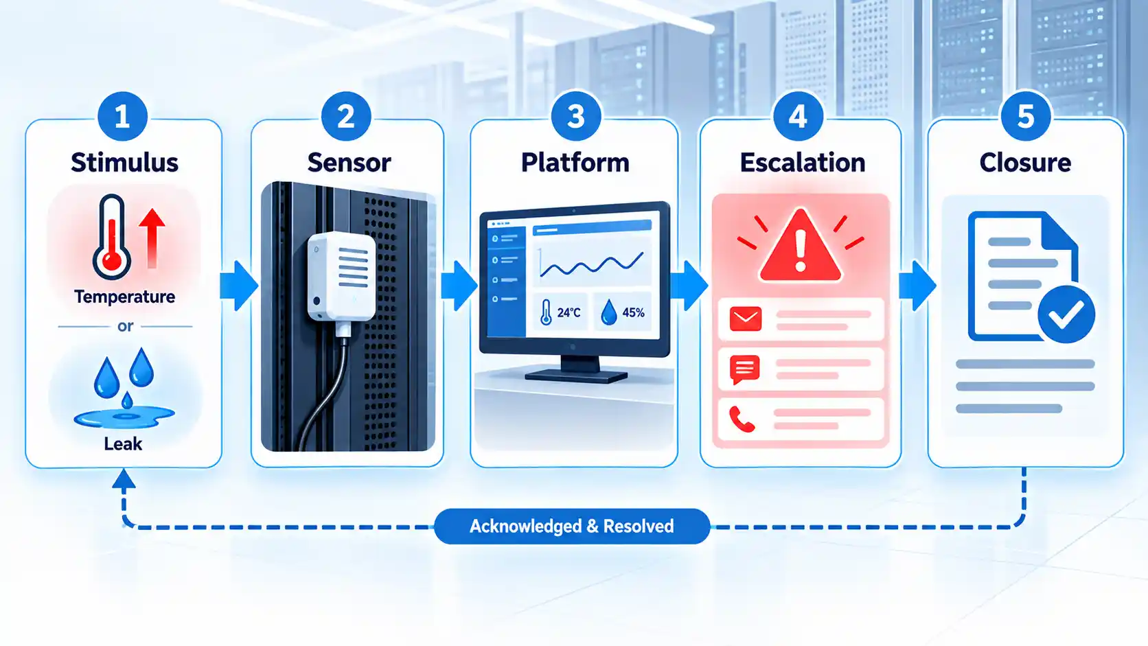
Use a controlled and safe test condition appropriate to the sensor. Confirm that the displayed value belongs to the correct location, uses the correct unit, and carries a current timestamp. Then test warning and critical states, each notification channel, escalation after non-acknowledgment, event logging, and restoration to normal status.
A simulated platform alarm does not prove that the physical probe works. Likewise, applying a test condition at the probe does not prove that an after-hours responder will receive and understand the message. Both parts require verification.
Calibration compares measuring equipment with a suitable reference so that systematic error and measurement uncertainty can be understood. The U.S. Department of Energy’s calibration guidance states that calibration requirements should cover the quantities, ranges, conditions, accuracy, and uncertainty needed by the use case. Laboratory accreditation alone does not establish that a particular calibration falls within the laboratory’s accredited scope.
Set the calibration or comparison interval from the manufacturer’s guidance, drift history, operating conditions, consequence of error, and any applicable quality requirement. If two colocated probes gradually diverge, investigate rather than averaging them automatically. One may be drifting, exposed to a local heat source, or positioned differently enough to measure a real variation.
Maintain an inventory containing each sensor’s identifier, model, location, measurement range, installation date, configuration, firmware where applicable, calibration status, battery or power source, and replacement history. Preserve commissioning and alarm-test records so later reviewers can distinguish an environmental incident from a measurement failure.
Verify the result
- Each displayed sensor identity matches its documented physical location.
- Values, units, and timestamps remain correct from the probe through the monitoring platform.
- Warning, critical, missing-data, power-loss, and communication-loss conditions produce the intended alarms.
- The primary responder can acknowledge an event, and failed acknowledgment reaches the next responsible contact.
- Battery-backed or independent paths continue operating during the failures they are meant to report.
- Test results, exceptions, corrective actions, and restoration are recorded.
7. Use Trends to Improve Cooling and Coverage
Recorded data should support decisions about airflow, cooling, maintenance, and sensor placement. A long record has little value if the organization never reviews it.
Establish a normal baseline for representative operating states. Compare environmental readings with information technology load, cooling-unit status, door activity, maintenance, outdoor conditions where relevant, and power events. Examine the duration and distribution of excursions rather than relying only on daily minimum and maximum values.
For example, repeated upper-rack temperature increases after workloads move to a particular row can indicate recirculation or inadequate air delivery. If the room-average sensor remains stable, the difference confirms why inlet-level coverage matters.
Do not raise cooling setpoints based solely on a comfortable room average. Resolve hotspots and confirm that representative equipment inlets remain within the selected operating target. Current ASHRAE guidance for high-density facilities recommends granular inlet monitoring and thermally segmented zones as part of managing demanding rack loads.
High-density or liquid-cooled equipment can require additional measurements such as coolant supply and return temperature, flow, pressure, coolant quality, and leak state. Select these variables from the equipment and cooling-system specifications. Air measurements may still be necessary for components that remain air-cooled.
Review coverage after any material change to rack contents, blanking panels, containment, cabling, cooling equipment, liquid connections, or workload distribution. A sensor plan describes the facility at a point in time, not forever.
Environmental Monitoring Implementation Checklist
Use this sequence to turn the guidance into an operating monitoring program. The scale of each step should match the facility and the consequence of a missed event.
- Inventory the assets and consequences. Record critical equipment, dependencies, locations, service owners, and the operational effect of overheating, moisture, leaks, contamination, or supporting-system failure.
- Confirm environmental limits. Obtain the current manufacturer specifications and identify the applicable equipment classes, preferred operating targets, allowable boundaries, and special restrictions.
- Map each risk to a measurement. Select temperature, moisture, airflow, leak, power, or contamination monitoring only where the reading can reveal a defined failure mode or support a response.
- Survey and instrument representative locations. Measure rack inlets and likely failure points, include abnormal or high-load zones, and use temporary surveys where necessary to choose permanent locations.
- Configure actionable alarms. Establish warning, critical, rate-of-change, missing-data, power, and communication states with suitable persistence, hysteresis, ownership, and escalation.
- Protect the monitoring path. Check power, communications, storage, time synchronization, access control, local visibility, and backup arrangements from each sensor to the responder.
- Commission the complete chain. Test physical sensing, displayed values, thresholds, notifications, acknowledgment, escalation, records, and restoration under controlled conditions.
- Maintain measurement confidence. Track calibration, comparison checks, batteries, firmware, configurations, probe condition, and communication health according to risk and manufacturer guidance.
- Review trends and incidents. Correlate readings with cooling, power, workload, maintenance, and layout changes, then correct recurring hotspots, blind spots, or nuisance alarms.
- Reassess after change. Repeat the risk and placement review whenever equipment, workloads, room layout, containment, cooling, plumbing, or response responsibilities change.
Common Monitoring Failures and How to Correct Them
The room temperature is normal, but a rack reports high inlet temperatures
Check probe identity and position, then inspect for recirculated exhaust, missing blanking panels, obstructed vents, inadequate cold-air delivery, and recent workload changes. Compare top, middle, and bottom inlet readings before increasing room-wide cooling.
Two nearby sensors disagree
Confirm that they are genuinely exposed to the same conditions. Check mounting, direct airflow, heat sources, timestamps, units, configuration, and calibration status. Compare both with a suitable reference instead of assuming that the average is correct.
The system produces frequent nuisance alarms
Review the event history and determine whether the cause is normal short-duration activity, unstable control, poor placement, an incorrect equipment range, or a drifting sensor. Adjust persistence and hysteresis only after confirming that doing so will not conceal a fast harmful change.
A reading appears stable for an unusually long time
Check its timestamp, polling status, gateway connection, battery, sensing circuit, and local display. Configure explicit stale-data and communication-loss alarms so an old value cannot appear to be a healthy current measurement.
An alarm was generated, but nobody responded
Verify the contact route, duty schedule, message content, acknowledgment mechanism, and escalation timer. Test the process during the hours when the facility is unattended. Environmental alarm troubleshooting should include the people and communications path, not only the sensor platform.
Wireless probes fail or drain batteries unexpectedly
Inspect radio coverage, interference, reporting frequency, temperature effects, firmware, battery specification, and the path to the gateway. Evaluate wired and wireless sensor networks by installation constraints and failure behavior, not convenience alone.
An alarm occurs during planned maintenance
Confirm that the event is associated with authorized work and that real hazards remain visible. Use time-limited maintenance handling with a named owner and automatic expiry. Avoid broadly disabling alarms or leaving temporary thresholds in place after the work ends.
Conclusion
Reliable environmental monitoring connects representative measurements with equipment-specific limits and a tested response process. Place sensors at rack inlets and physical failure points, treat missing data as a fault, and verify that every important alarm reaches someone able to act.
The program should evolve with the facility. Changes to equipment density, airflow, cooling, liquid systems, room layout, or responsibilities can invalidate yesterday’s sensor plan even when every device still appears online.

💬 Comments